Close
Light Gauge Steel Framing Villa Roof System
Light Gauge Steel Framing Villa Roof System
9.1 - General provisions
9.1.1 Roof load-bearing structures of light steel villas can adopt trusses or inclined beams, the upper end of which is supported on the roof spine of the clasped section.
9.1.2 Structural panels shall be laid on the upper strings of light steel villa roof truss or roof steel belt bracing rods shall be set up. When the roof truss is supported by steel belt bracing, the bracing and all roof truss should be connected with screws at the intersection. The thickness of the cross steel strip brace should not be less than 0.8mm. The lower chord of roof truss should be laid structural plate or set longitudinal support rod.
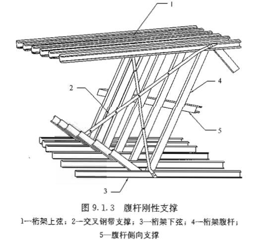
9.1.3 Longitudinal lateral support and cross support should be set at the belly pole of light steel villa roof truss (Figure 9.1.3).
9.1.1 At present, roof load-bearing structures used for cold-formed thin-wall steel structures are mainly divided into two forms: truss and inclined beam. The truss system mainly bears the axial force while the inclined beam mainly bears the bending moment.
9.1.3 When the strut is long, the lateral support can effectively reduce the calculated length of the strut outside the plane of the truss. Cross support can ensure the integrity of the belly strut system, which is conducive to maintaining the overall stability of the light steel villa roof truss.
9.2 Design Requirements
9.2.1 In the design of light steel villa roof truss, the adverse effect of internal force change caused by wind suction should be considered, and the load component coefficient of permanent load should be set as 1.0.
9.2.2 When calculating the internal forces of each member of the roof truss in the light steel villa, it can be assumed that the roof truss chord is a continuous rod and the connection point between the belly rod and the chord is a hinge.
9.2.3 The calculated length of light steel villa roof truss members can be adopted according to the following provisions:
In the roof truss plane, the calculated length of each member can be taken as the distance between the nodes of the member.
2 Outside the roof truss plane, the calculated length of each member can be adopted according to the following provisions:
1) When the upper chord of the roof truss is laid on the structural face plate, the length of the upper chord shall be calculated and the spacing between the screw connections of the chord shall be 2 times; When the purlin constraint is used, the distance between purlins of upper chord attemper length can be taken;
2) When the roof truss has no lateral support, calculate the length of distance between desirable nodes; When lateral support is provided, calculate the distance between the desired length node and the lateral support point of the roof truss ventral bar;
3) When the lower chord of the roof truss is laid on the structural face plate, the calculation length of the lower chord shall be 2 times of the spacing between the chord screw connections; When longitudinal bracing members are used, the length of the lower chord can be calculated as the distance between the lateral fixed points.
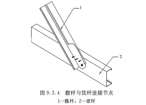
9.2.4 When the belly rod of light steel house truss is connected back to back with the chord (Figure 9.2.4), the influence of external eccentricity should be considered when designing the belly rod. The eccentricity should be calculated according to the bending member bending around the weak axis. The distance between the outer surface of the section web of the belly rod and the centrepiece should be taken.
9.2.5 The number of connecting point screws in the main body of light steel villas shall be determined by the calculation of shear and pull resistance.
9.2.2 The simplified mechanical model in this article is completely consistent with the actual roof truss structure. In practical engineering, the chord is a continuous member, while the ventral rod is connected to the chord through a screw. The bearing capacity and overall stability of the chord are calculated in accordance with the relevant provisions of bending members in Article 6.1.5 of this code, and the calculation of the belly rod is in accordance with the relevant provisions of articles 6.1.2 and 6.1.3 of this code for axial bearing members.
9.2.3 The roof of cold-formed thin-wall steel structure (light-steel villa) differs from other types of roof in that the winding rod will lay structural panels such as oriented strand board (OSB), which has a strong constraint effect on the buckling of the upper flange of the winding rod. To calculate the length, take twice the spacing of the screws in consideration of the possibility of failure of a single screw in the process of screw playing. In order to ensure the reliability of the stability calculation of the chord, take twice the spacing of the screws.
9.2.4 The ventral bar is usually calculated according to axial compression or axial tension members, without considering the influence of eccentricity.For the problem of the correlation between the overall stability and the local stability of the thin-walled members in the light steel villas, the calculation and test show that when the belly rod and chord are connected back to back, the existence of the off-face eccentricity will reduce the bearing capacity of the belly rod by about 10%-15%, so the eccentricity should be considered in the calculation.
9.3 Roof truss node structure
9.3.1 When there is no concentrated load at the roof ridge, the ventral rod of the roof truss and the chord rod can be directly connected at the roof ridge (FIG. 9.3.1a); When there is concentrated load at the roof ridge, it should be connected by connecting plate (FIG. 9.3.1b and C). When connecting with the connecting plate, the connecting plate shall be flanged and strengthened (FIG.
9.3.1b) or reinforced (FIG. 9.3.1c) shall be set.The number of connecting screws between chord rod and ventral rod or nodal plate should not be less than 4. When using direct connection, the roof ridge must be provided with longitudinal rigid support.

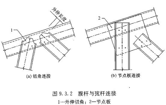
9.3.2 When the belly rod and chord are connected in the middle of the main roof truss of light steel villas, they can be directly connected or connected through the connecting plate. When the roof truss ventral rod is directly connected to the chord rod, the end of the ventral rod can be cut Angle, the length of the extension of the cutting Angle should not be more than 30mm, the end of the ventral rod should be set within the line of the crimping side
Place not less than 2 screws (FIG. 9.3.2a); When connecting plates are used between roof truss and chord, there shall be at least one ventral rod directly connected to chord < FIG. 9.3.2b).When necessary, the joint of the chord can be strengthened with a split closed section, and the length of the stiffener should not be less than 200mm.
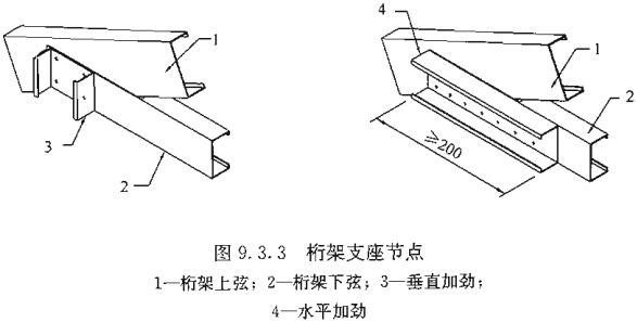
9.3.3 When the upper chord and the lower chord are connected in the same direction with an open connection, it is appropriate to set vertical or horizontal stiffeners on the lower chord web. The thickness of the stiffeners should not be less than the thickness of the chord member (Figure 9.3.3). The lower flange at the bearing joint of the lower chord of the truss should extend to meet the lower flange of the upper chord.When horizontal stiffeners are used, the length of the horizontal stiffeners shall not be less than 200mm. In the beam type structure, the inclined beam should be connected with the house back beam through the connector.
9.3.4 When the roof truss of the main body of the light steel villa is connected with the top guide beam of the external wall, three-way connectors or other types of tensile connectors should be used to ensure the reliable transmission of vertical and horizontal forces between the roof truss and the wall. The number of connecting screws should not be less than 3.
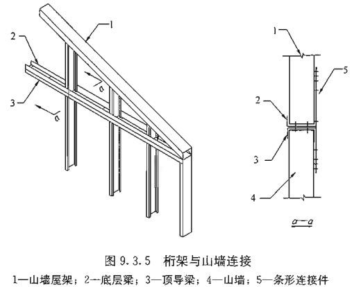
9.3.5 The abutments of the gable roof truss should correspond to the gable posts up and down, and bar connectors with spacing no more than 2m should be set along the outside (FIG. 9.3.5).
9.3.6 When there is a reliable basis, other structural methods can be adopted for the main roof truss structure of the light steel villa.
9.3.1 The test shows that when there is a concentrated load near the roof ridge, if the stiffness of roof ridge joints is weak, the failure of joints will precede the instability failure of members. Therefore, according to the load situation, to choose the corresponding roof ridge joint form. In FIG. 9.3.1, (a) is applicable to the roof without concentrated load, (c) is applicable to the roof with concentrated load, and (b) node stiffness is between the two.
9.3.2 The existence of horizontal stiffening can increase the torsion stiffness of the lower chord, and prevent the torsion buckling failure of the chord at the connecting part when the load transmitted from the abdominal bar to the chord is large. Considering that there is a possibility of instability of the outrigger plate when screws are set only within the range of the outrigger Angle, it is stipulated that no less than 2 screws should be set within the connecting line of the winding edge of the end of the abdominal rod.
9.3.5 The strip connector on the main body of the light steel villa can resist the upward wind suction and the upward pulling force generated by the stripping action, so as to enhance the integrity of the wall and roof system and prevent the separation of the roof and wall under the action of hurricane and strong earthquake.
Related Recommendations
C Z Purlin Roll Forming Machine
C Z Purlin Machine, also called fast change Steel Purlin Making Machine or C & Z Shape Interchangeable Rolling Machine, can be used to produce both C channel and Z channel with various sizes, in different thickness, and with punch on web and flange side
Lipped Channel Purlin Roll Forming Machine
The CZ Purlin Roll Forming Machine is used to produce both C and Z purline on one machine Adjust from one shape to the other, one operator o...
Novotek Purlin Roll Forming Machine Factory
We are the biggest cz purlin making machine factory in China, and is the only one who can manufacture the fully automatic purlin roll forming machine
Product Catalog
- C/Z Purlin Machine
- Fully Automatic CZ Purlin Roll Forming Machine
- Semi Automatic CZ Purlin Roll Forming Machine
- CZ Purlin Roll Forming Machine (400A)
- CZ Purlin Roll Forming Machine (400/4mm)
- Light Gauge Steel Framing Machine (100m/min)
- Pre-Cut CZ Purlin Machine
- Pre-Punch CZ Purlin Machine
- CZ Purlin Stacking Machine
- Stacking Machine (C Purlin)
- Steel Strapping Machine (Purlin/Pipe Packing Machine)
- U Purlin Machine (40m/min)
- U V L Channel Roll Forming Machine (65m/min)
- PGC/ PGU Purlin Roll Forming Machine
- Multi Profile Purlin Roll Forming Machine
- CZ Purlin Roll Forming Machine 320A
- Z Purlin Roll Forming Machine
- Hat Profile Roll Forming Machine
- Solar PV Support Roll Forming Machine
- Large High Speed Purlin Line
- High Speed CUZ Purlin Roll Forming Machine
- Full Automatic Stud Track Roll Forming Machine
- C Purlin Roll Forming Machine with Stacker (5mm)
- Non-stop Cutting C Purlin Roll Forming Machine
- CZU Purlin Roll Fomring Machine with Fly Cut
- Coil Slitting Machine (1-3mm)
- Completely Automatic CU Purlin Roll Forming Machine
- Fly Punch & Fly Cut Purlin Machine
- 5mm C450 Purlin Machine with Stacking Machine
- Box Beam Roll Forming Machine
- Beam Profile Roll Forming Machine
- Roll Forming Machine
- Deck Sheet Roll Forming Machine
- Roof Sheet Roll Forming Machine (30m/min)
- Corrugated Sheet Roll Forming Machine (35m/min)
- Roof Sheet Roll Forming Machine with Stacker
- Double Layer Roll Forming Machine
- Three Layers Roll Forming Machine
- Guardrail Roll Forming Machine
- Standing Seam Roll Forming Machine
- High Speed Roofing Panel Roll Forming Machine
- Downspout Roll Forming Machine
- Roof Sheet Crimping Curving Machine
- Mesh Welding Machine
- Metal Floor Decking Roll Forming Machine
- K-Span Roll Forming Machine
- H Beam Welding Machine
- Cable Tray Roll Forming Machine
- Hydraulic Folding Machine
- Barrel Corrugated Machine
- Roof Panel Roll Forming Machine
- Stud Track Roll Forming Machine
- Glazed Tile Roll Forming Machine
- Door Frame Roll Forming Machine
- PV Support Bracket Roll Forming Machine
- Mini Coil Slitting Machine
- EPS Sandwich Panel Machine
- PU Sandwich panel machine
- Rockwool Sandwich Panel Machine
- Sandwich Panel Band Saw Cutting Machine